Antenna Feeder calibrated cable
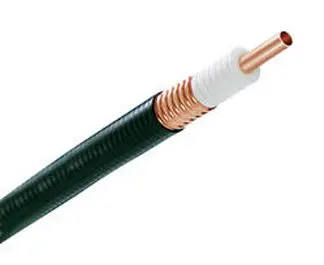
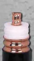
CELLFLEX® 7/8″ low loss flexible cable
FEATURES
The reduced attenuation of CELLFLEX® coaxial cable results in extremly efficient signal transfer in your RF system, especially at high frequencies.
The solid outer conductor of CELLFLEX® coaxial cable creates a continuous RFI/EMI shield that minimizes system interference.
Special low VSWR versions of CELLFLEX® coaxial cables contribute to low system noise.
- Outstanding Intermodulation Performance
CELLFLEX® coaxial cable’s solid inner and outer conductors virtually eliminate intermods. Intermodulation performance is also confirmed with state-of-the-art equipment at the RFS factory.
Due to their low attenuation, outstanding heat transfer properties and temperature stabilized dielectric materials, CELLFLEX® cable provides safe long term operating life at high transmit power levels.
- Wide Range of Application
Typical areas of application are: feedlines for broadcast and terrestrial microwave antennas, wireless cellular, PCS and ESMR base stations, cabling of antenna arrays, and radio equipment interconnects
| NFORMATION |
| Applications |
|
Main feed line, intended for outdoor usage |
|
| STRUCTURE |
| Size |
|
7/8 |
| Inner Conductor |
mm (in) |
9.1 (0.358) |
| Inner Conductor Material |
|
Copper Tube |
| Dielectric |
mm (in) |
21.5 (0.846) |
| Dielectric Material |
|
Foam Polyethylene |
| Outer Conductor |
mm (in) |
25.2 (0.992) |
| Outer Conductor Material |
|
Corrugated Copper |
| Jacket |
mm (in) |
27.8 (1.094) |
| Jacket Material |
|
Black Polyethylene |
|
| TESTING AND ENVIRONMENTAL |
| Phase Stabilized |
|
Phase stabilized and phase matched cables and assemblies are available upon request. |
| Compliance |
|
DIN EN ISO 9001:2015ISO 14001:2015
RoHS 2011/65/EU – China RoHS SJ/T 11364-2006
REACH (EC 1907/2006)
UL1581 – UV Resistance Jacket
IEC 60754-1/-2 |
| Installation Temperature |
°C(°F) |
-40 to 60 (-40 to 140) |
| Storage Temperature |
°C (°F) |
-70 to 85 (-94 to 185) |
| Operation Temperature |
°C(°F) |
-50 to 85 (-58 to 185) |
|
| ELECTRICAL SPECIFICATIONS |
| Impedance |
Ω |
50 +/- 1 |
| Maximum Frequency |
GHz |
5 |
| Velocity |
% |
88 |
| Capacitance |
pF/m (pF/ft) |
74 (22.5) |
| Inductance |
uH/m (uH/ft) |
0.185 (0.056) |
| Peak Power Rating |
kW |
85 |
| RF Peak Voltage |
Volts |
2920 |
| Jacket Spark |
Volt RMS |
8000 |
| Inner Conductor dc Resistance |
Ω/1000 m (Ω/1000 ft) |
2.04 (0.62) |
| Outer Conductor dc Resistance |
Ω/1000 m (Ω/1000 ft) |
2 (0.61) |
| Passive Intermodulation PIM |
min. dBc |
-160 |
| Return Loss (VSWR) Performance |
|
Standard 20dB (1.222) / Premium 23/24dB (1.152/1.135) on specified frequencies |
|
| MECHANICAL SPECIFICATIONS |
| Cable Weight, Nominal |
kg/m (lb/ft) |
0.35 (0.23) |
| Minimum Bending Radius, Single Bend |
mm (in) |
120 (5) |
| Minimum Bending Radius, Repeated Bends |
mm (in) |
250 (10) |
| Bending Moment |
Nm (lb-ft) |
13 (10) |
| Tensile Strength |
N (lb) |
1440 (324) |
| Recommended / Maximum Clamp Spacing |
m (ft) |
0.8 / 1 (2.75 / 3.25) |
|
| ATTENUATION @ 20°C (68°F) AND POWER RATING @ 40°C (104°F) |
| Frequency, MHz |
dB per 100m |
dB per 100ft |
Power, kW |
| 1 |
0.11 |
0.03 |
85.00 |
| 100 |
1.13 |
0.35 |
8.8 |
| 200 |
1.62 |
0.49 |
6.14 |
| 450 |
2.47 |
0.75 |
4.02 |
| 700 |
3.12 |
0.95 |
3.19 |
| 800 |
3.36 |
1.02 |
2.96 |
| 900 |
3.57 |
1.09 |
2.78 |
| 1800 |
5.21 |
1.59 |
1.91 |
| 2000 |
5.53 |
1.68 |
1.80 |
| 2200 |
5.83 |
1.78 |
1.70 |
| 2400 |
6.12 |
1.86 |
1.62 |
| 2700 |
6.54 |
1.99 |
1.52 |
| 3000 |
6.94 |
2.11 |
1.43 |
| 3500 |
7.57 |
2.31 |
1.31 |
| 4000 |
8.17 |
2.49 |
1.22 |
| 5000 |
9.30 |
2.83 |
1.07 |
|