Blog
How much distance does a radio transmitter cover?
How much distance does a radio transmitter cover?
COVERAGE IN KILOMETERS FOR AN FM TRANSMITTER/ANTENNA SYSTEM
Guide to predict how many kilometers are covered by an FM Transmitter associated with an antenna system
Common questions :
How to decide how much power I need for an FM transmitter?
What is the best antenna system and cable to be used?
How much Power does a radio station need to cover a specific area?
I need an FM Transmitter to cover 90 kilometers.
Please quote me a complete radio station to cover 150 kilometers.
Please quote me a complete radio station for a community radio.
We’re in the process of starting a community broadcasting and would like to know how much to budget for such venture!
These are some of the common requests that we receive from our customers.
They need professional advice from industry experts to decide which option is best for them.
With the following guide we will try to help them answer these questions.
The most difficult decision involves the power range of the FM Transmitter and the Antenna System type.
Most of the time the doubts are not related to Radio Studios.
In these cases it is easier, without being a specialist in the sector, to orient oneself towards which type of equipment to buy, and most of the time the choice depends exclusively on the available budget.
It is more difficult for the Transmitter System to decide the right power of the FM Transmitter and the type of Antenna to be used.
What follows is a simplified guide with some advice and data; although not exhaustive, it is a useful list of the factors that will determine the coverage or the distance, in kilometers, that can potentially reach the FM signal.
Factors that determine the coverage of an FM Transmission system.
The analysis below is based on mathematical calculations, but in summary they demonstrate that the coverage of a transmitting system depends on the power of the transmitter, the antenna system, the height at which the antennas are mounted and the type of area to cover.
The best advice can give you is to build a system with a good transmitter, but to not overlook the type of the antenna and the height of the installation point.
With regard to the power of the transmitter, to make a prediction of the potential distance that it can reach, there is a memo-technical rule that can be applied: if we need to double the distance covered we need to quadruple the power of the transmission system.
In other words: distance by two, power by four.
There are many factors that determine how far the FM signal radiated by the transmitter/antenna system will go.
A good estimate can be reached by considering four of them:
- The effective radiated power (ERP)
- The antenna height
- The shape of the terrain
- The area to be covered: rural, urban or large town.
The first parameter we need to consider is the ERP, that is the effective radiated power of the total transmitting system.
To calculate the ERP you need to know the following factors:
- The output power of the transmitter
- The losses of the coaxial cable used to connect the transmitter to the antenna.
- The length of the coaxial cable.
- The type of the antenna system: dipole vertical polarization, circular polarization, single antenna, systems with 2 or more antennas, etc.
- The gain of the antenna system in dBb. The gain can be positive or negative.
The ERP formula is:
ERP = Transmitter power in Watt x 10^((Gain of the antenna system in dBb – looses of the cable) / 10)
Example:
Power of the FM Transmitter = 1000 Watt
Type of antenna = 4 bay dipole vertical polarization with a gain of 8 dBb
Type of cable = low looses 1/2”
Length of cable = 30 meters
Attenuation of the cable = 0,69dB
ERP = 1000W x 10^(8dB – 0,69dB)/10 = 3715W
So the system described in the formula would effectively provide aproxximately 3 times the transmitter power to 3,715 Watts ERP with a coverage of 152 kilometers.
It must be noted that this is only a theoretical calculation: in order to arrive inside the houses and pass through obstacles much more power is needed to cover this distance.
How to choose the right connector and cable for transmitter and antenna.
| Alluminium Dipole Antenna | |||
| BAYS | POWER UP TO | CONNECTOR | CABLE |
|---|---|---|---|
| 1 | 800W | N | RG213 |
| 2 | 1600W | 7/16” | 1/2” |
| 4 | 3200W | 7/8” | 7/8” |
| Stainless Steel Dipole Antenna with Connector 7/16” | |||
| BAYS | POWER UP TO | CONNECTOR | CABLE |
| 1 | 2000W | 7/16” | 1/2” |
| 2 | 4000W | 7/8” | 7/8” |
| 4 | 8000W | 7/8” | 7/8” |
Attenuation of the Coaxial Cable
What follows is a table that describes the typical attenuation and the max power allowed by the different Coax Cables typically used:
| Attenuation at 100MHz | Attenuation db/100m | Attenuation db/30m | Maximum Averange Power Rating |
|---|---|---|---|
| RG213 | 6,2 | 1,86 | 1000 |
| RG214 | 7,5 | 2,25 | 800 |
| RG218 | 3 | 0,9 | 3500 |
| CLX 1/4″ (Foam) | 4,5 | 1,35 | 1500 |
| CLX 1/2 (Foam) | 2,3 | 0,69 | 3400 |
| CLX 7/8 (Foam) | 1,2 | 0,36 | 7500 |
| CLX 1 5/8 (Foam) | 0,7 | 0,21 | 15000 |
The total power radiated is necessary to win the attenuation of the air on the free space, called “Free space attenuation in dB”.
The attenuation of the air on the free space is 72,4dB x 1 kilometer.
This attenuation increases by 6 dB each time the distance doubles, so, for 2km it is 78,4dB, for 4km 84,4dB, and so on.
This means we have loose 4 times the power each time the distance is doubled.
Table of Free-space attenuation at 100MHz
| Free-space attenuation (dB) at 100MHz | |
|---|---|
| Distance (Km) | Attenuation (dB) |
| 1 | 72,4 |
| 2 | 78,4 |
| 3 | 81,9 |
| 4 | 84,4 |
| 5 | 86,6 |
| 6 | 88 |
| 7 | 89,3 |
| 8 | 90,5 |
| 9 | 91,5 |
| 10 | 92,4 |
| 15 | 95,9 |
| 20 | 98,4 |
| 25 | 100,4 |
| 30 | 101,9 |
| 35 | 103,3 |
| 40 | 103,4 |
| 50 | 106,4 |
| 100 | 112,8 |
Once we know the ERP there are many other factors to consider:
- The height of the antenna above the area to be covered. A way to understand this point is to imagine how far the transmitting antenna can effectively see. If you stand in the same point the antenna is mounted and look out with a pair of binoculars, wherever you can see it is possible to transmit to. This can be 5 or 6 kilometers if you are standing up on a flat terrain or up to 30 or 40 kilometers if you are on a mountain top.
- The height of the trees in the area around the antenna.
- The height of the buildings around the antenna.
- The type of terrain flat or hills.
- The sensitivity of the receiver.
- The proximity of other radio stations broadcasting in the same frequency, for example the antenna may be able to see as far as 20 kilometers, but if another station is on the same frequency 20 kilometers away, it will block/interfere with the signal.
In general, one of the most important points is the topography of the terrain: hills, mountains, large buildings of the city, pass through the windows or walls to come inside the houses….
The C.C.I.R. says the minimum level of signal needed to have a good reception on the different areas is as follows:
Rural areas = 48 dBμV
Urban areas = 60 dBμV
Large towns = 70 dBμV
The following table illustrates the aproximate coverage in Kilometers of a rural area with different values of ERP:
| Watts in ERP | Kilometers Rural area |
|---|---|
| 10 | 8 |
| 30 | 13 |
| 50 | 17 |
| 100 | 24 |
| 300 | 42 |
| 500 | 54 |
| 1000 | 76 |
| 2000 | 108 |
| 4000 | 152 |
| 6000 | 187 |
| 10000 | 241 |
The following table illustrates, taking into account the terrestrial curve, the distance covered with different heights of the antenna system:
| Height (meters) | Distance (km) |
|---|---|
| 3 | 6 |
| 10 | 11 |
| 20 | 16 |
| 30 | 20 |
| 60 | 28 |
| 100 | 36 |
| 300 | 62 |
| 500 | 80 |
| 1000 | 113 |
| 2000 | 160 |
| 3000 | 196 |
The FM signal will propagate as far as there is optical visibility.
If you look at the horizon with binoculars, the maximum distance we can look at is called the “Line of sight”.
The FM signal does not go beyond this distance.
This is why the height of the antenna is so crucial.
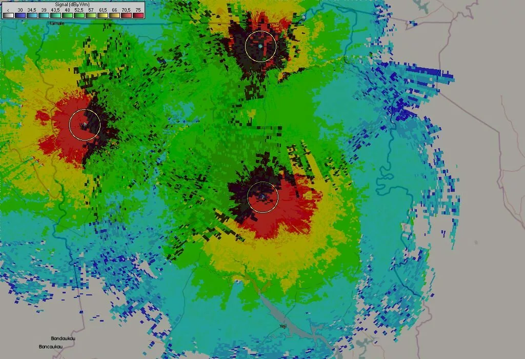
Example of coverage of the same FM Transmission system installed at different heights:
You could have two different radio stations using a 1000 Watt FM transmitter: one of them with a 30 meter tower in a flat terrain will cover 20 kilometers, while the other with the antenna on a 500 meters hill will cover 80 kilometers.
It must be known that the range can only be estimated and results can not be guaranteed until after a given system has been tested in real practice.
In conclusion, to know the effective coverage of a transmission system we must take all these factors into account, especially the Effective Radiated Power, the Antenna height from the terrain and the type of area to cover: Rural, Urban, Towns or Large Towns
If the antenna can see 20 kilometers away, but 10 Watt ERP are used, it’s probable that no more than 8 kilometers will be covered, because there is not enough power to propagate the signal as far as 20 kilometers.
If 100 Watt ERP are used, it’s very likely that 20 kilometers of range will be reached because 100 Watt ERP are able to propagate a strong signal for 20 kilometers.
If 1000 Watts of ERP power are used, it is very probable that the signal will reach 20 kilometers, but moreover it will help to penetrate eventual obstacles.